This is one of the very few radios I have built that I tried to make nice-looking. I'm not a craftsman. I had found a bunch of antique parts at swap meets over the years, and this was a good chance to use some of them. The case was a Bailey's sherry tin I bought at a junk store. I painted it black wrinkle and filed some notches that I filled with red enamel for the dial markers. The main tuning and bandspread knobs were cleaned up and the white markings repainted. It all came out looking pretty good.
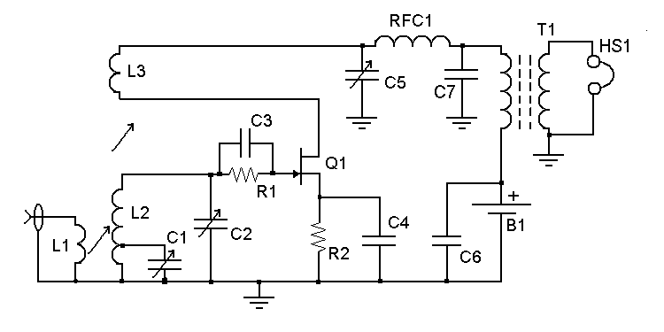
The circuit was intended as a sort of test bed, and the circuit board has jumpers on it that can reconfigure the way the output is hooked up. It can either be taken from the source circuit as in Kitchin's radios or through a transformer in the drain circuit as was usual in the old days. The throttle capacitor is a Hammarlund unit that I bought at Henry Radio in Anaheim when I was about 13. It was intended to be used in a regenerative receiver from the 1958 ARRL Handbook that I never built.
The main tuning capacitor is an antique Pilot unit from the 20's and its plates bounce around a lot, so you have to be careful about banging the operating table when the receiver is in use. The tuning range is about 3.2 to 14.2MHz with a single coil, so it covers 4 (or I guess 5 if you count 60m) ham bands and all the SWBC bands in that range, etc. The background noise is easily audible if the receiver is used with a good antenna, and some pretty weak signals can be copied. Stability is pretty good, though with this wide tuning range the bandspread is too much on 80m and not enough on 20m.
Notice that this detector uses an RC network in the gate circuit. Kitchin used it, so I did too, but I have since found that sensitivity is better without it so my newer designs don't have these parts. I think their inclusion in FET detector designs is because there has been a perception in the ham community that detection occurred in tube-type detectors by means of rectification in the grid circuit, more or less in the manner of the famous grid-leak detector. A tube is just a "glassfet," so a FET should work the same way. But FET "grids" don't "leak" (especially if they are MOSFET's.) I think that detection in an Armstrong circuit is a result of natural nonlinearities in the amplifier that are made even worse by the regeneration. Let me know if you think I'm wrong about this.
I intended to use this radio with an RF amp for isolation and an audio amp to raise the output to a usable level, but I found that I don't need either under most conditions. It's big fun to operate CW with a total of one transistor in the receiver system.


